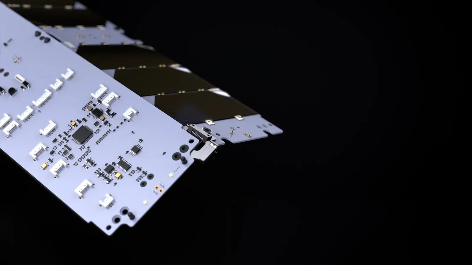
Single-wing array
One deployable wing extends from the spacecraft. Panel segmentation is a separate design choice.
FULLSUNS configuration guide | Configuration Example
Discuss configuration
Discuss wing configuration, dimensions, electrical interfaces and deployment method for your mission.
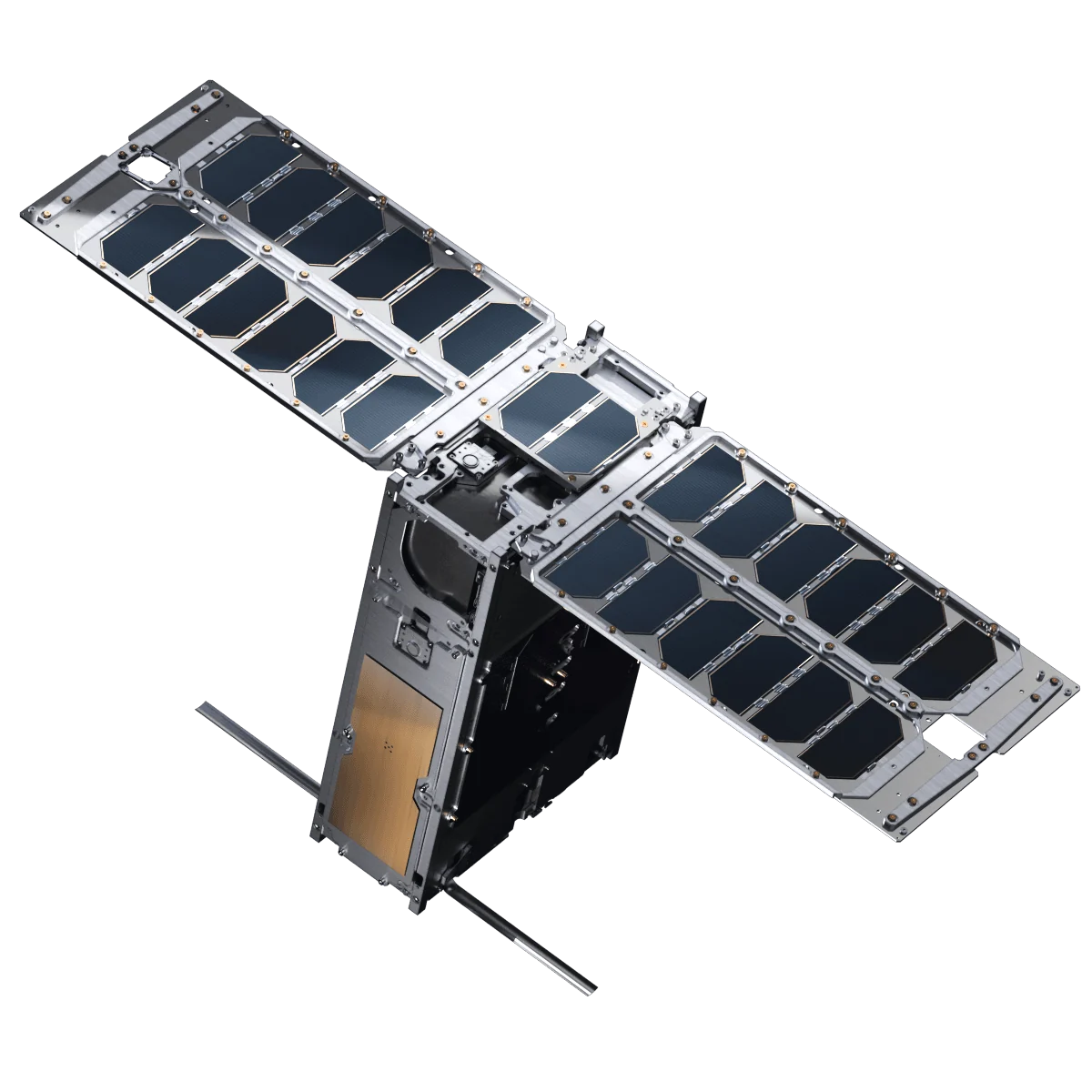
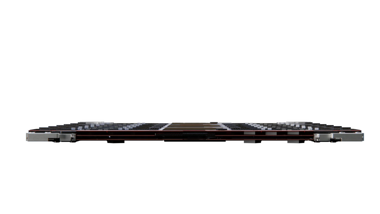
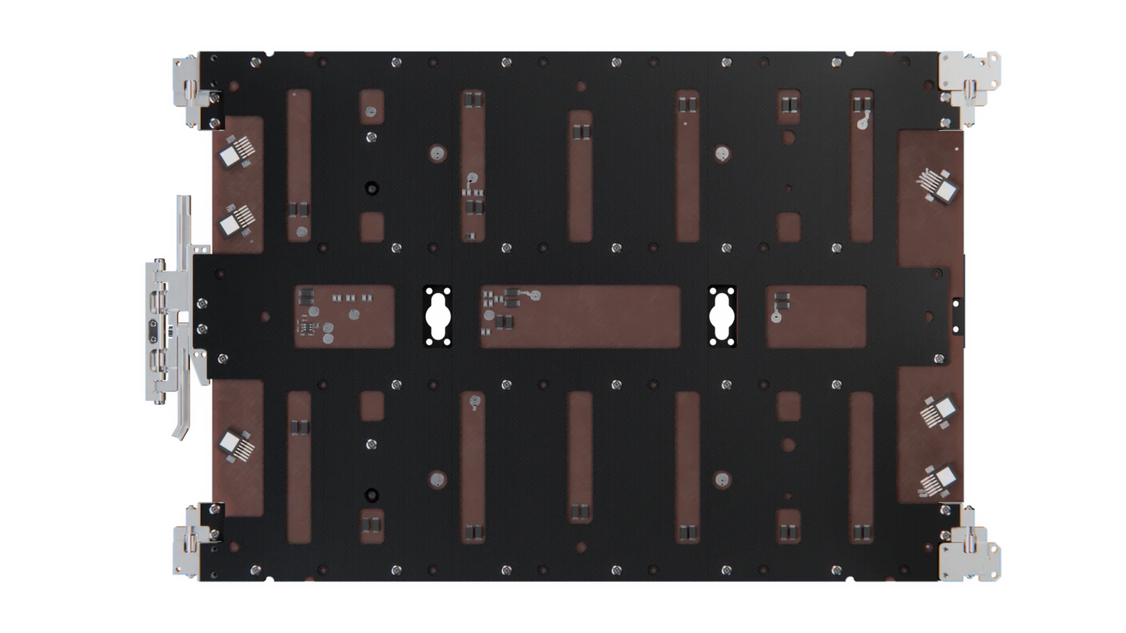
Wing count and folding segment count describe different aspects of the design. These images are configuration references, not a stock-product catalogue.
One deployable wing extends from the spacecraft. Panel segmentation is a separate design choice.
FULLSUNS configuration guide | Configuration Example
Discuss configuration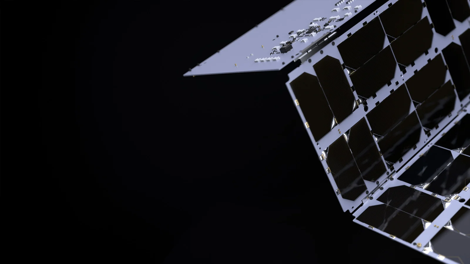
Two wings extend from the spacecraft. Each wing may contain one or multiple panel segments.
FULLSUNS configuration guide | Configuration Example
Discuss configuration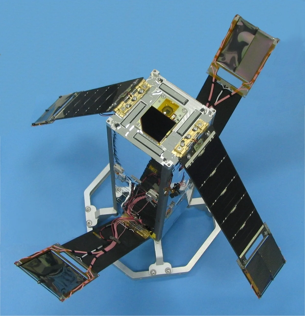
More than two wings are evaluated against spacecraft geometry and deployment clearances.
FULLSUNS configuration guide | Configuration Example
Discuss configuration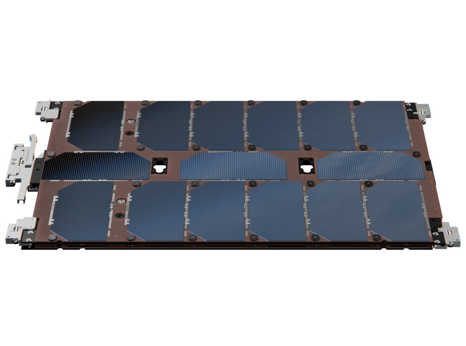
Panel segments fold within a wing. Segment count does not define the number of wings.
FULLSUNS configuration guide | Configuration Example. Panel-level reference; folding geometry is project-specific.
Discuss configurationFixed and body-mounted panels are covered separately. Satellite Solar Panels
Use the following items to define the proposed assembly. Included components, supplier responsibilities and engineering scope are confirmed in the project proposal.
Model selection, cell layout and panel electrical configuration.
Substrate, panel frame and supporting structure requirements.
Hinge geometry, travel and deployment approach.
Launch restraint, release trigger and deployed locking interfaces.
Wiring, connector definition and deployment routing.
Spacecraft attachment points and optional sensor accommodation.
| Parameter | Selection basis |
|---|---|
| Cell type & efficiency | Selected model and its confirmed datasheet; no array-wide efficiency claim |
| Nominal & maximum output power | Project-specific; evaluated under agreed mission conditions |
| Output voltage & channel configuration | Custom; matched to the electrical interface |
| Stowed & deployed dimensions | Custom; matched to the installation envelope |
| Total mass | Project-specific; calculated for the selected configuration |
| Release trigger signal | Project-specific interface matching |
| Antenna & other mounting interfaces | Subject to accommodation review |
| Orbital lifetime & environment | Project-specific; confirmed against mission requirements |
The proposal identifies which tasks are performed internally and which require an external laboratory. Test levels, facilities and acceptance criteria are agreed for the specific assembly; no blanket qualification or flight-heritage claim is implied.
Review stiffness, load paths and interface loads against the agreed model and load cases.
Define restraint, gravity compensation, deployment sequence and acceptance criteria for the configuration.
Agree illumination, temperature, circuit configuration and measurement points before comparing output.
Vibration, shock, acoustic and thermal-vacuum testing may be included in the project test plan after facility and configuration review.
The document set and release stage are defined in the agreed supply scope. Request available reference documents during the technical review.
30% triple-junction GaAs solar cell reference data. Electrical values are model-specific and subject to stated test conditions.
Download datasheet (PDF)Request configuration-specific drawings, an interface control document (ICD) and applicable test documentation. Availability and deliverables are agreed during technical review.
Request a Technical ProposalAvailability of certain products, configurations or technical data may be subject to applicable export-control, end-use and destination review.
Share what is known about your mission. Only name and email are required; technical fields may be left blank.