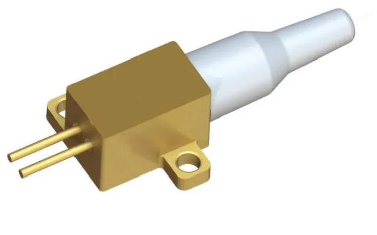
808 nm / 5 W semiconductor laser
- Wavelength
- 808 nm
- Optical output
- 5 W
Confirm input conditions, interfaces, cooling and configuration for the project.

Semiconductor lasers, laser drivers and packaged LPC receivers, alongside power management, photovoltaic testing and industrial measurement. Discuss component selection and integration for your operating conditions.
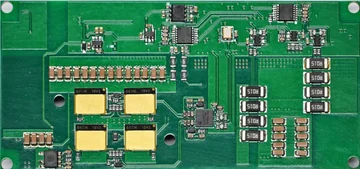 Laser driverElectrical supply & control
 Semiconductor laserElectrical-to-optical conversion
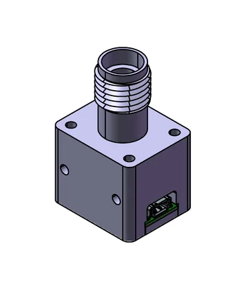 LPC receiverOptical-to-electrical conversion
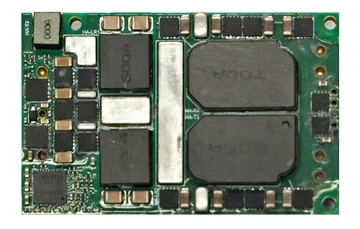 MPPT / DC-DCVoltage conversion & management
Select components by stage. Images show example products; confirm system configuration, interface compatibility and supply scope for your project.
No matching components
Match receiver wavelength, optical interface and optical power.
Confirm input conditions, interfaces, cooling and configuration for the project.
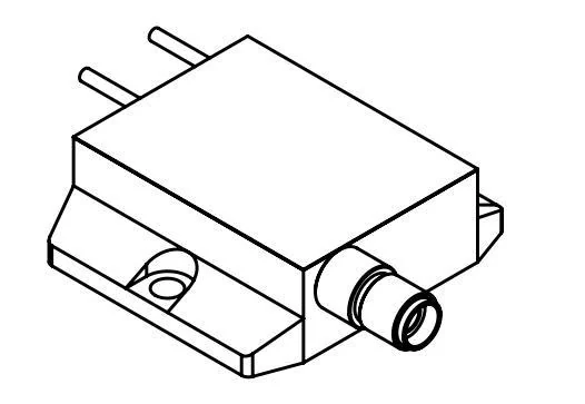
Confirm input conditions, interfaces, cooling and configuration for the project.
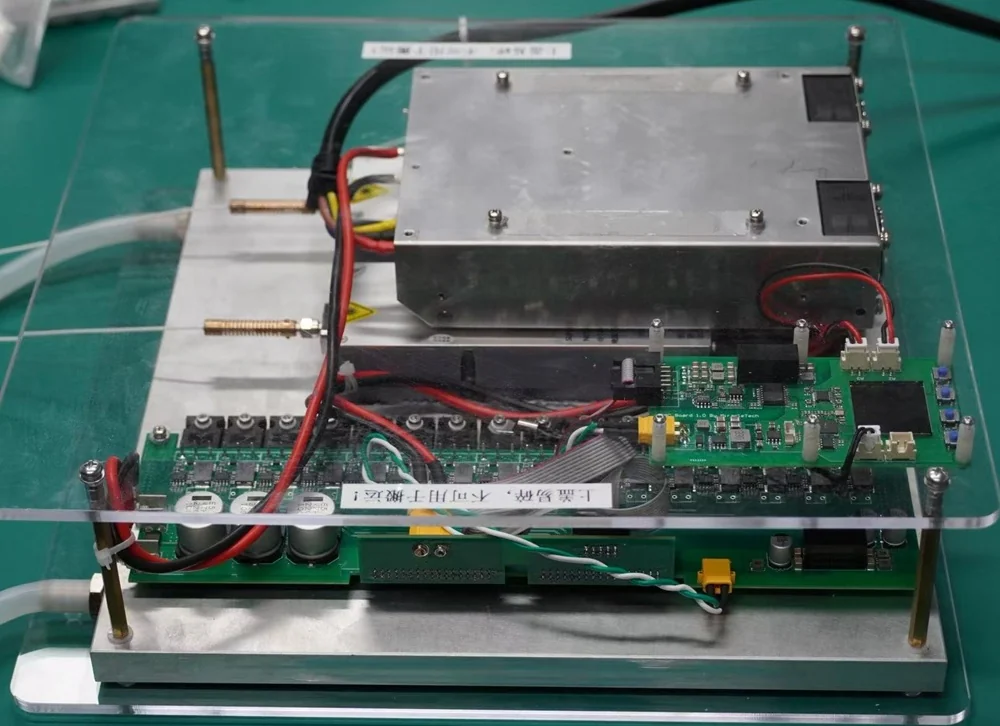
Liquid-cooled; wavelength depends on version. Confirm channel power allocation, optical interfaces and safety interlocks.
20 W is the typical laser optical output, not the electrical output of an LPC receiver. System selection must account for fiber and connector compatibility, transmission losses, cooling and receiver operating conditions.
Datasheet test condition: water temperature 25°C. A dash indicates a value not specified in the source specification.
| Parameter | Minimum | Typical | Maximum |
|---|---|---|---|
| Center wavelength | 803 nm | 808 nm | 813 nm |
| Optical output power | - | 20 W | - |
| Threshold current | - | 1.3 A | - |
| Operating voltage | - | 3.4 V | - |
| Operating current | - | 12 A | 14 A |
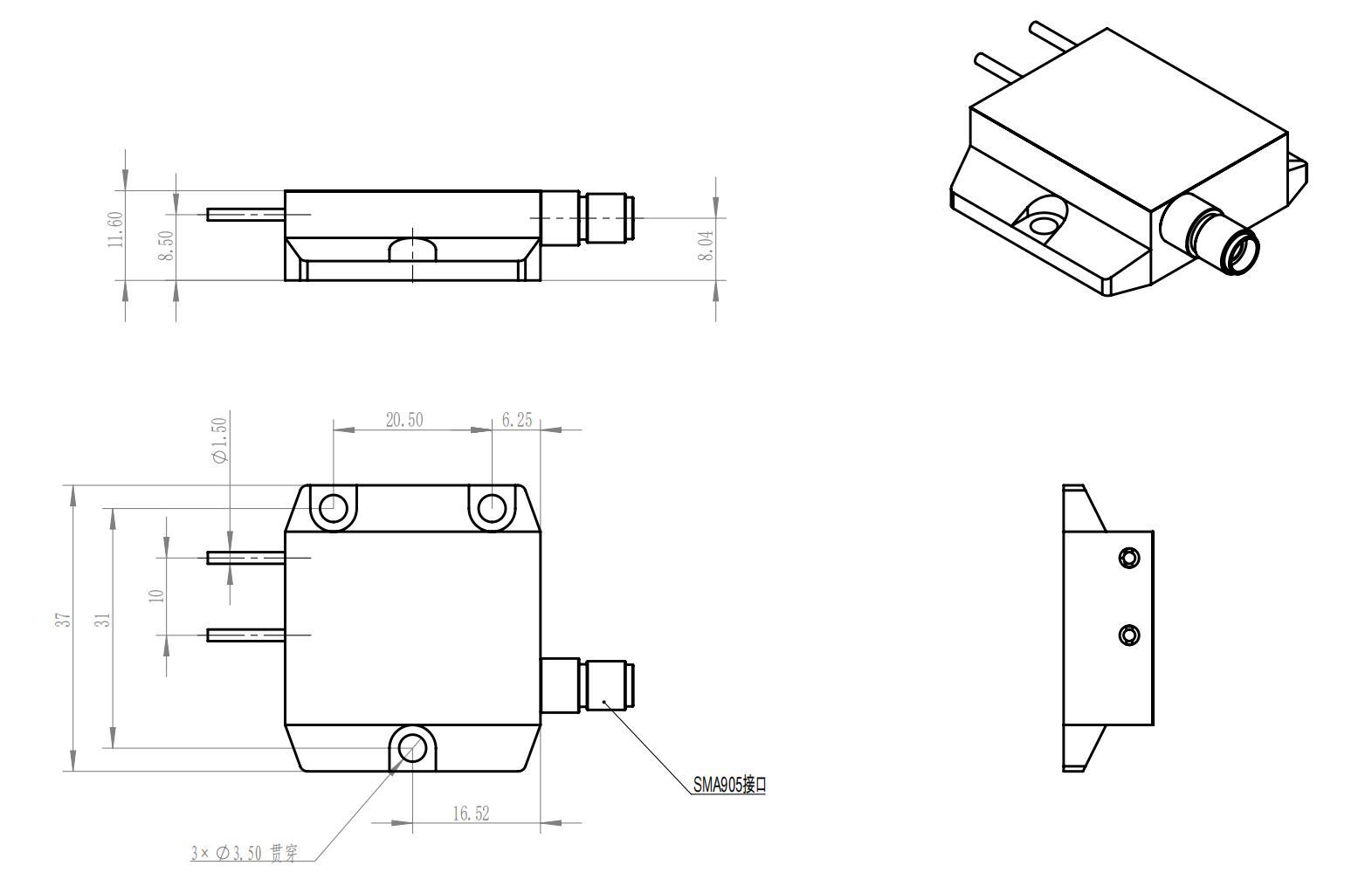
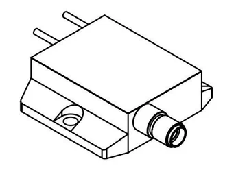
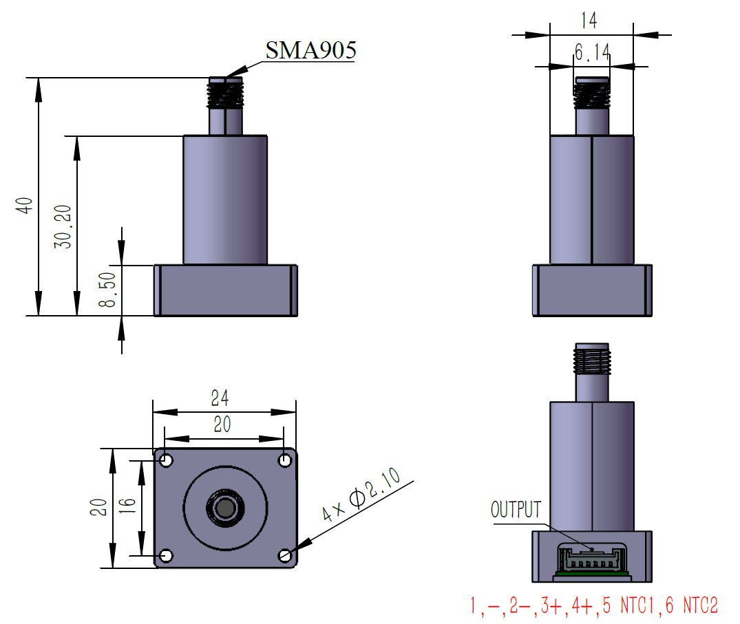
In the view with two leads on the left, the upper lead is pin 1 (LD−) and the lower lead is pin 2 (LD+). Mounting holes: 3 × Ø3.50 mm through-holes.
FULLSUNS English PDF · 3 pages · Specifications, dimensions and pinout
Select for load voltage, current, control and protection.
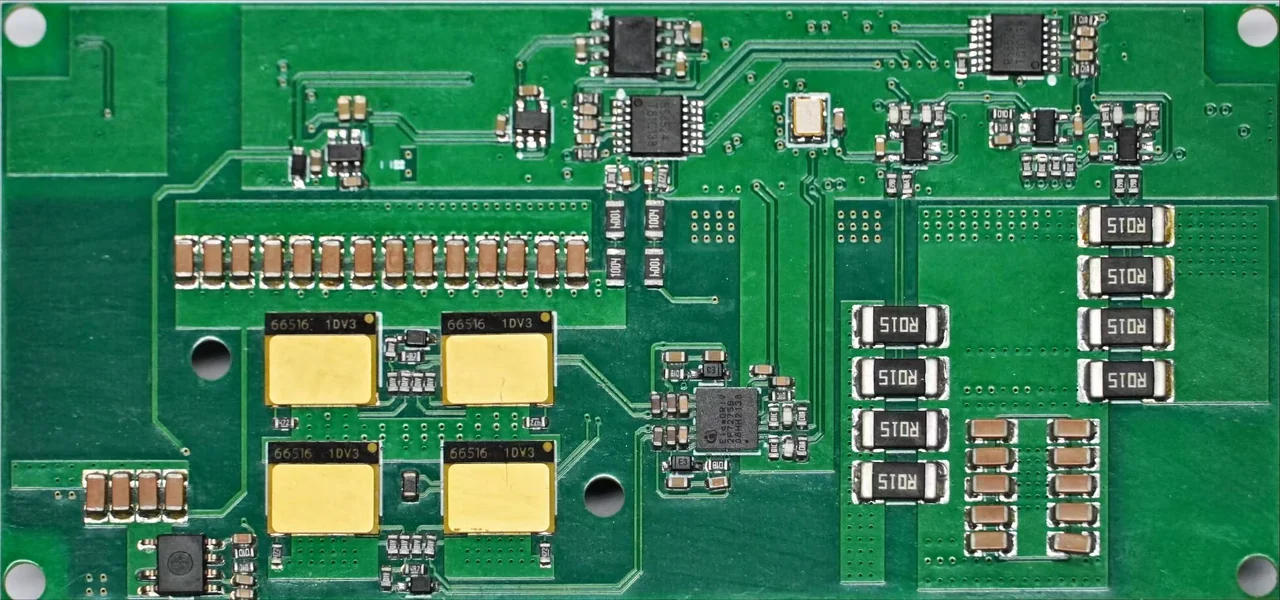
Voltage and current limits are not a guarantee of simultaneous full-scale output. Confirm input range, power envelope and protection.
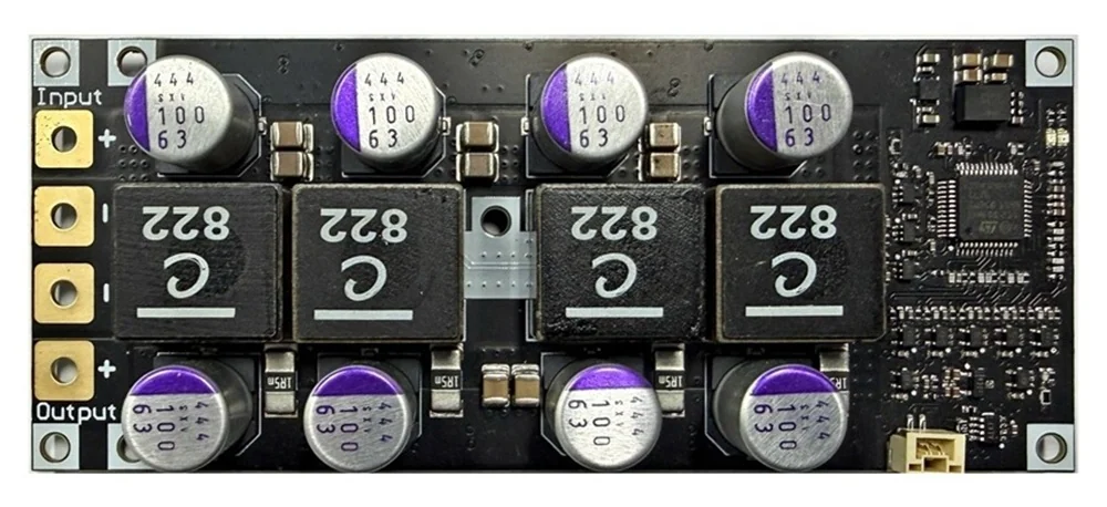
CC/CV control. Confirm continuous power, cooling and load transients.
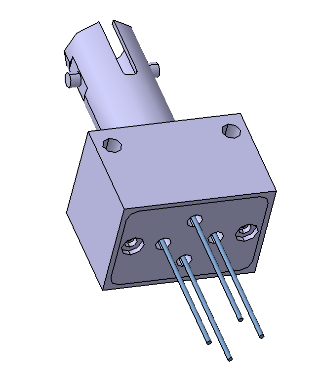
Integrate optical input, conversion cells, heat transfer and electrical terminals.
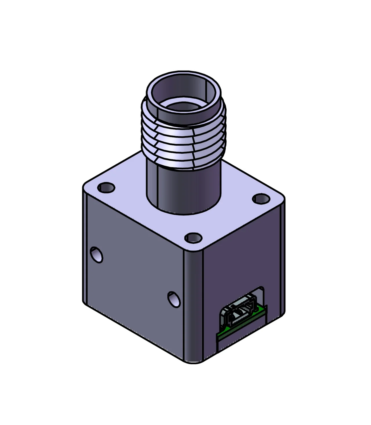
Confirm input conditions, interfaces, cooling and configuration for the project.
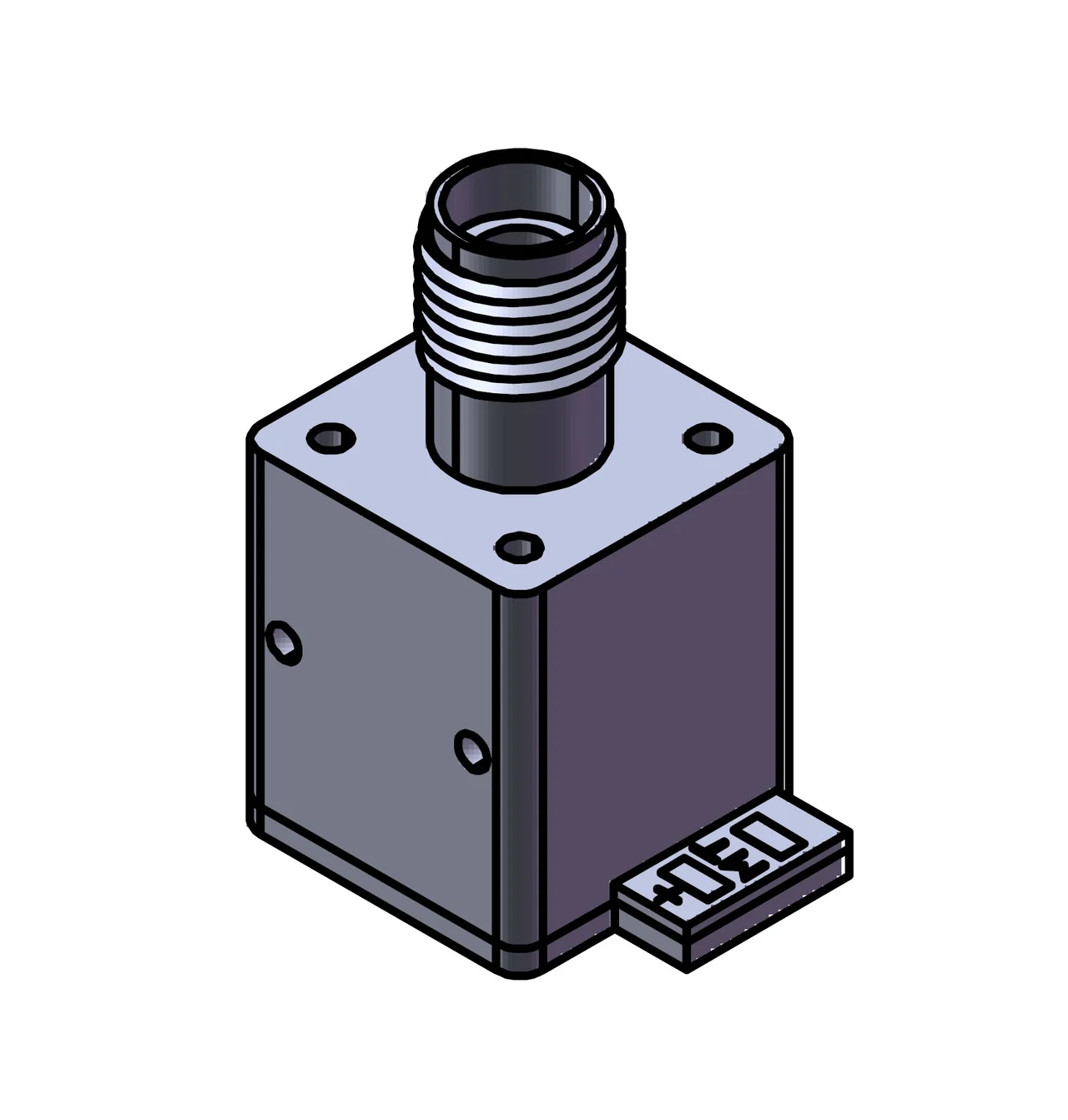
Confirm input conditions, interfaces, cooling and configuration for the project.
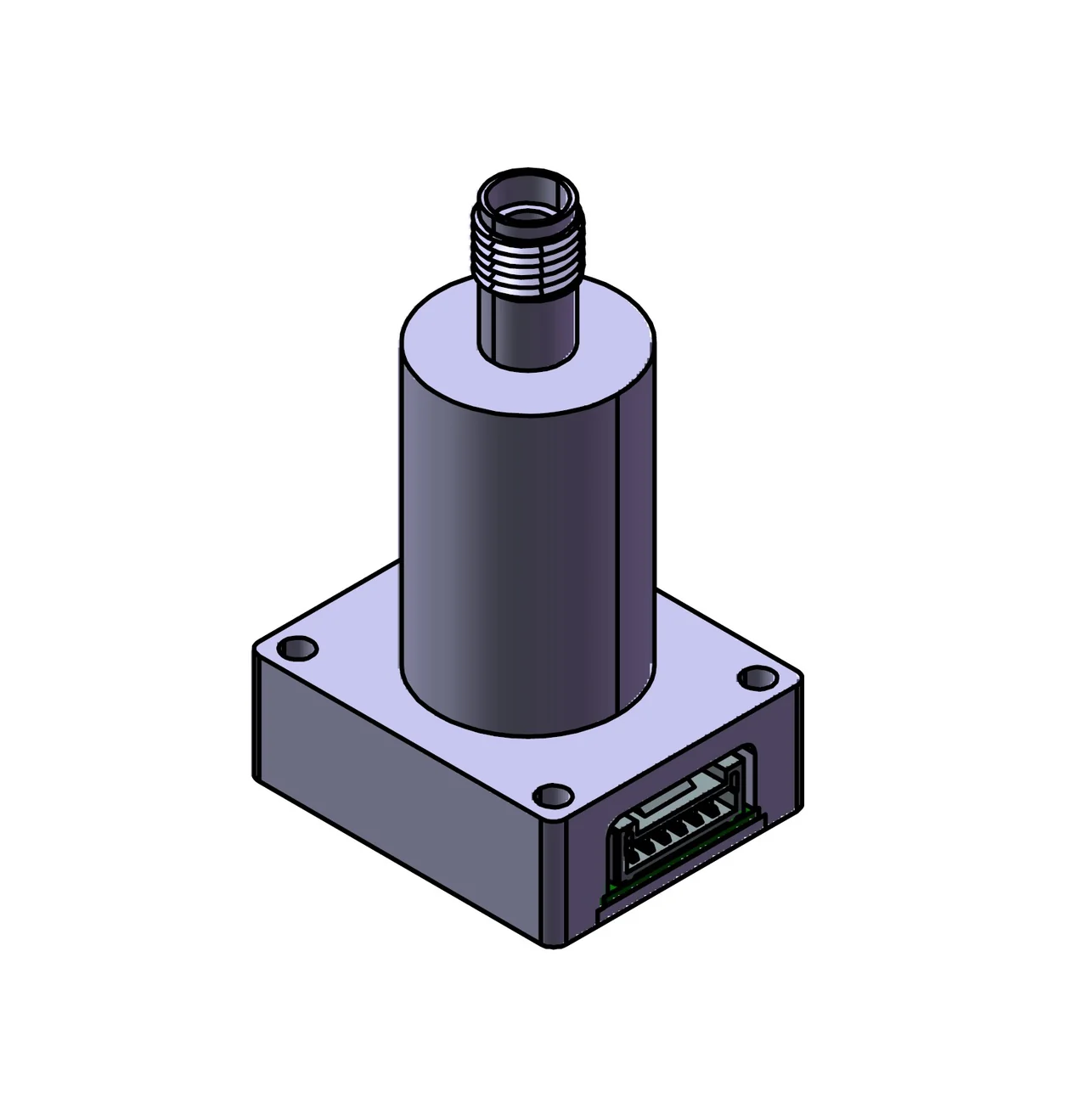
Typical maximum-power-point values at 25°C case temperature. Bottom heat sinking is required; output is not inherently regulated.
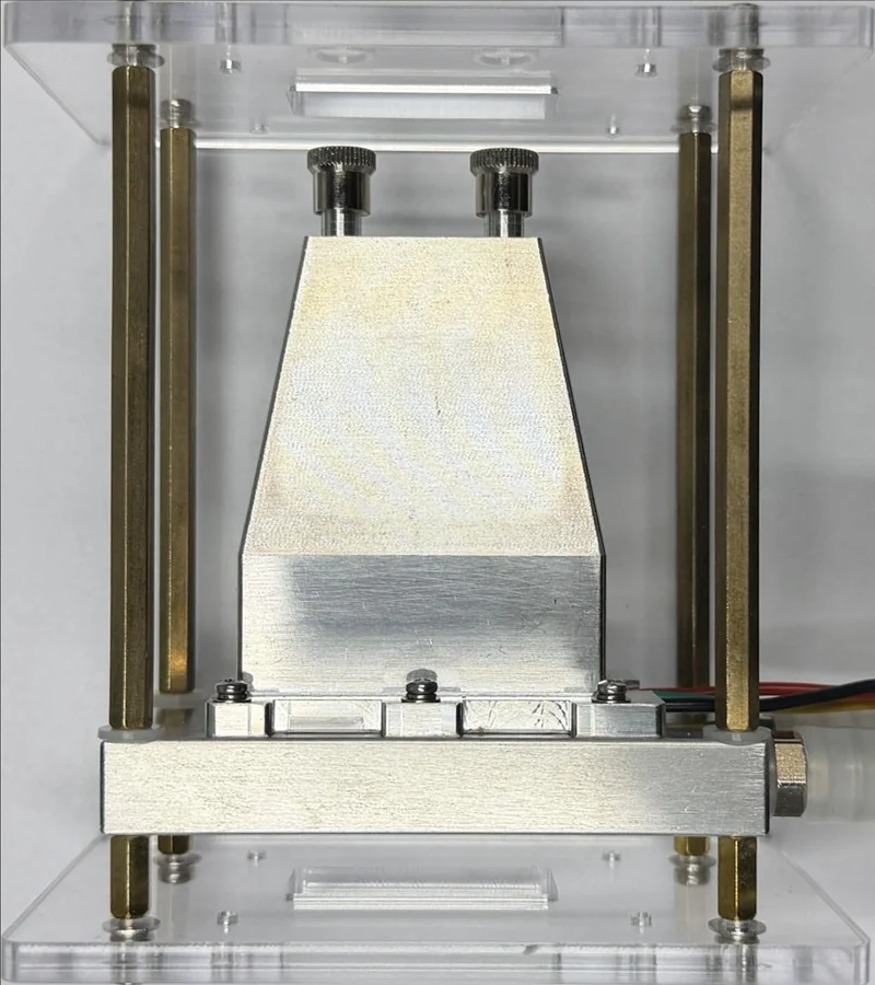
Air or liquid cooling by configuration. Electrical output depends on incident light, beam profile and temperature.
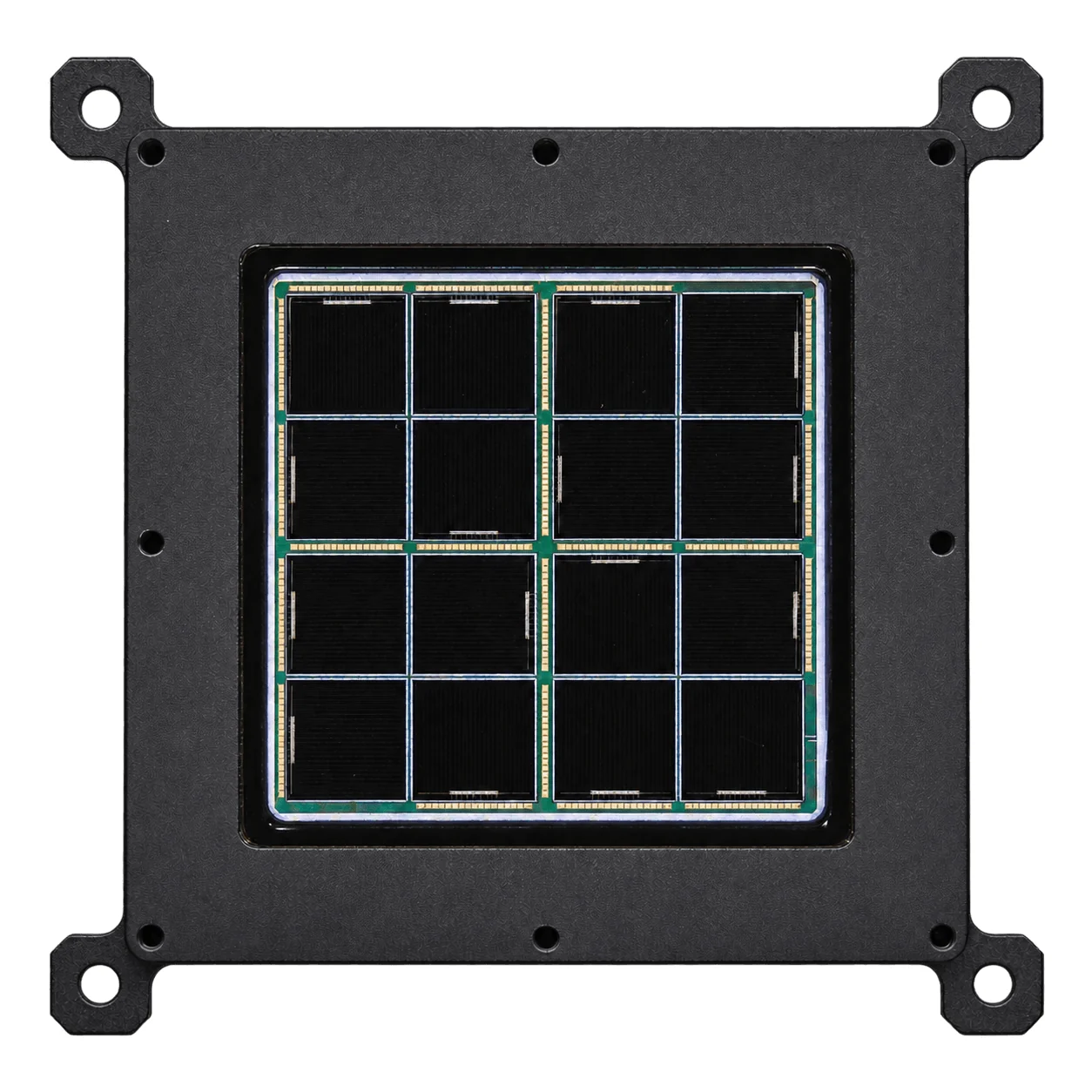
Select a wavelength-specific configuration; one module is not assumed to cover all listed wavelengths. Confirm optical input and cooling.
Electrical data: case temperature 25 °C. Characteristic curves: laser wavelength 808 nm.
| Optical input | Electrical power at MPP | Voltage at MPP | Current at MPP |
|---|---|---|---|
| 10 W | 5.40 W | 6.05 V | 0.893 A |
| 20 W | 10.79 W | 6.05 V | 1.784 A |
| 30 W | 15.92 W | 5.91 V | 2.693 A |
30 W is the stated maximum optical input. Bottom heat sinking must keep the case within its temperature limits. Match fiber coupling, load and voltage regulation to the actual system.
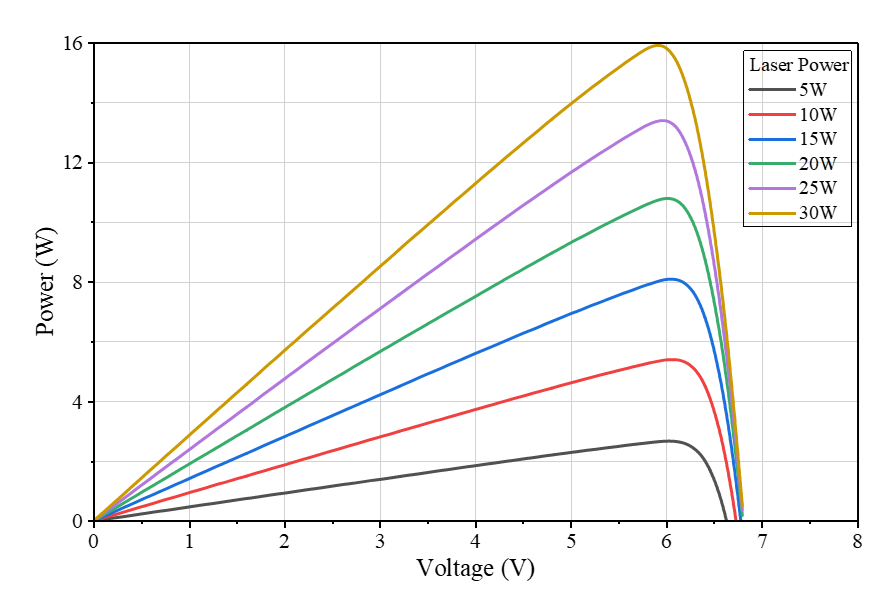
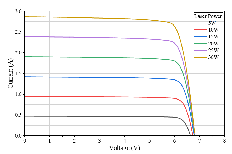
English PDF · Specifications, dimensions and characteristic curves
Match active area, electrical operating point and installation.
Confirm input conditions, interfaces, cooling and configuration for the project.
Confirm input conditions, interfaces, cooling and configuration for the project.
Confirm input conditions, interfaces, cooling and configuration for the project.
Configure by wavelength, active area, voltage and thermal design; confirm version-specific parameters.
Adapt voltage and specify MPPT, storage and protection as required.
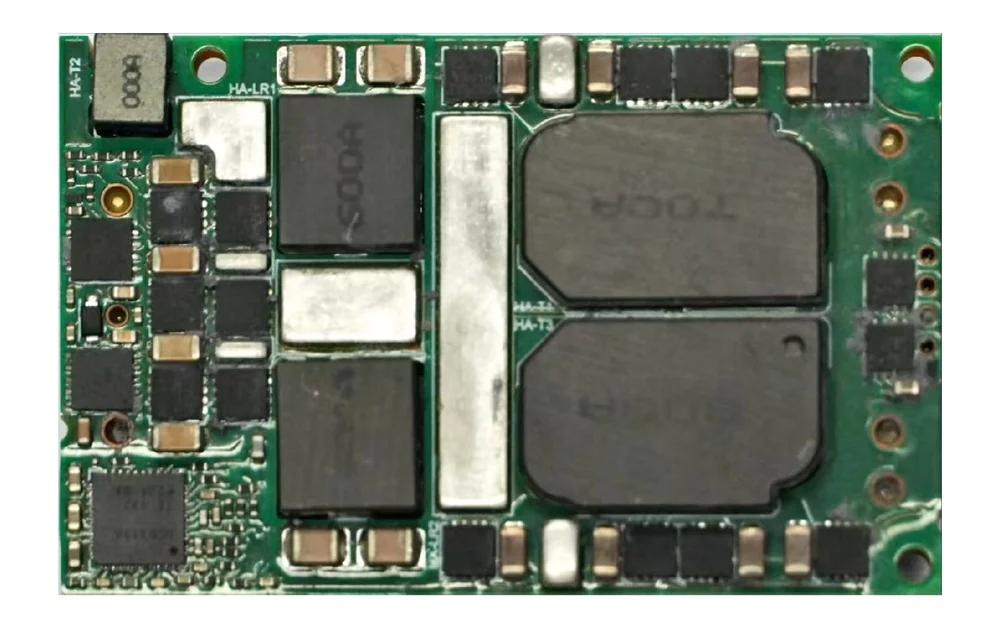
Quarter-brick format; verify power and current together against input, cooling and derating curves.
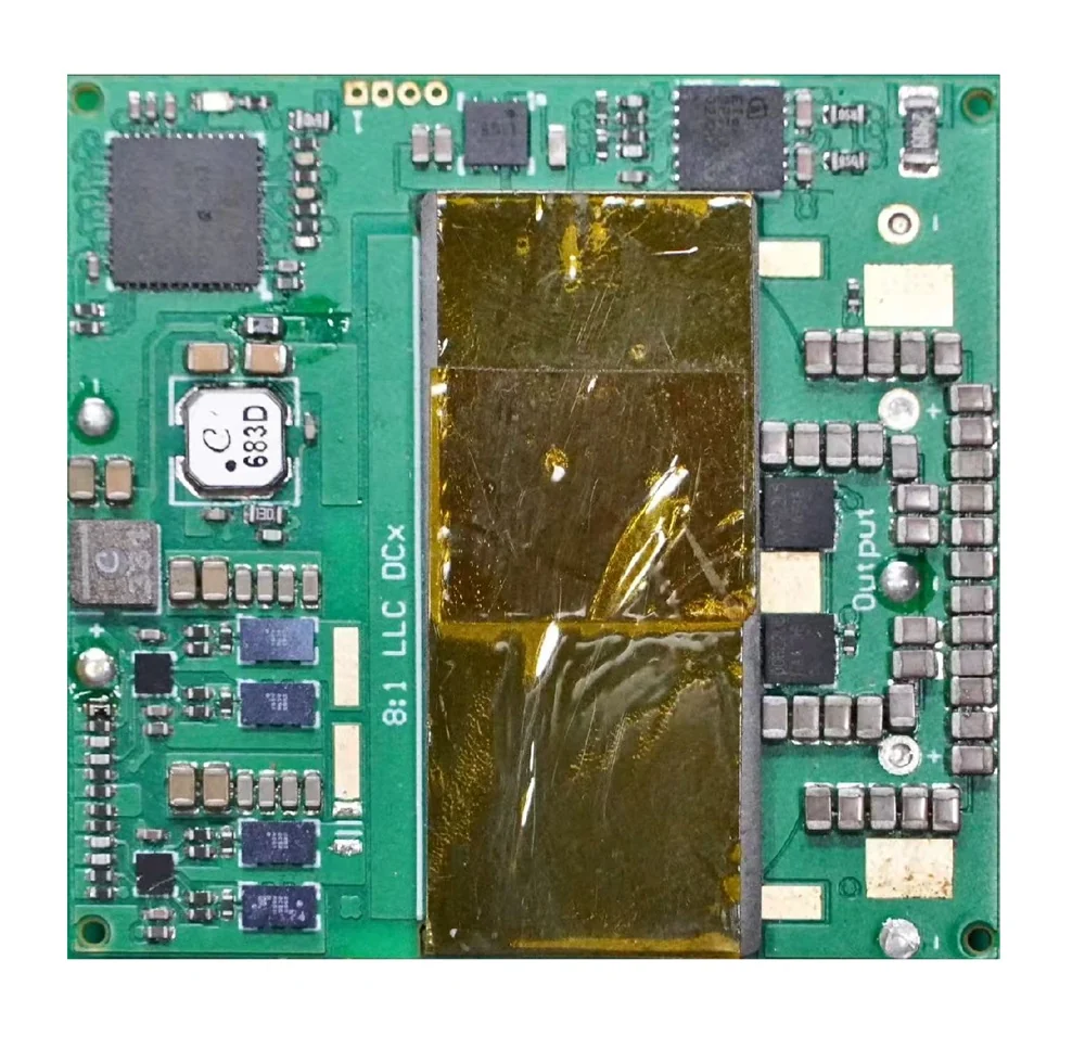
Confirm input conditions, interfaces, cooling and configuration for the project.
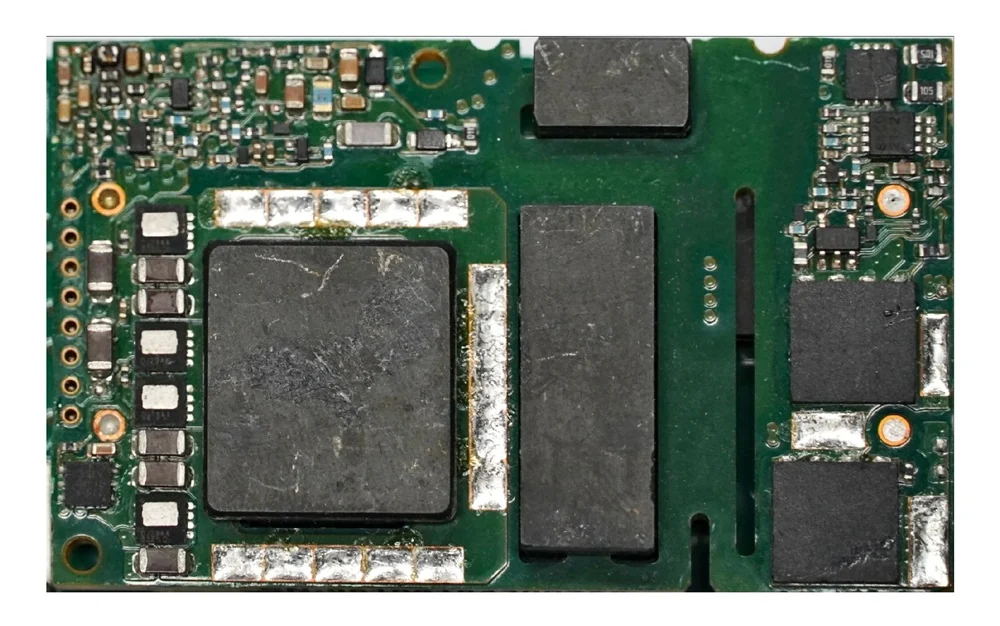
Confirm input conditions, interfaces, cooling and configuration for the project.
Match MPPT, regulation, charging and protection to the LPC I–V curve and load. Verify startup power and efficiency for the design.
Photovoltaic testing, semiconductor characterization and industrial acquisition.
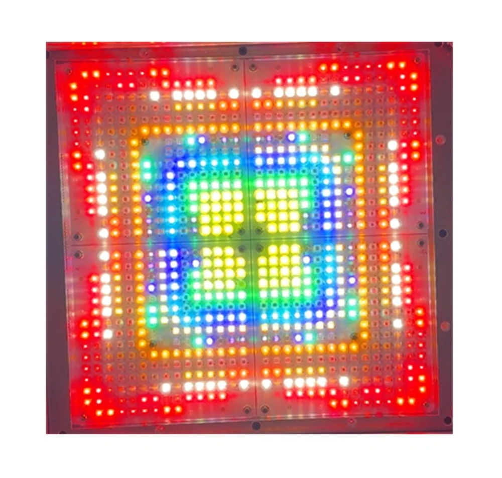
Programmable illumination with 1 ms to continuous operation. Confirm spectral match, uniformity and stability classification by test report.
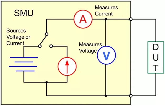
For semiconductor characterization and I–V measurement. Confirm voltage, current, power envelope and accuracy for the range and acquisition conditions. Image shows the measurement principle.
Configure temperature, voltage and current acquisition for the site: channels, isolation, accuracy, sampling and communication.
Match transmitter, optical link, receiver and power management. Check coupling and insulation for fiber systems; line of sight, beam footprint, alignment, obstruction detection and interlocks for free-space systems.
Discuss selectionEvaluate custom supplies against input range, output voltage/current, transient response, control, cooling and installation space.
Discuss selectionCombine solar simulation and source-measure instruments for the device under test, illumination conditions, I–V sweeps and measurement repeatability.
Discuss selectionIntegrate field temperature, voltage and current acquisition with defined channels, ranges, isolation, communication and installation conditions.
Discuss selectionProvide wavelength, optical or electrical power target, transmission path and distance, CW or pulsed operation, supply voltage, cooling, interfaces and sample quantity. For test equipment, include the device under test, range, accuracy and acquisition speed.
Discuss selectionNo. The laser rating is optical output. Electrical power at the load also depends on transmission, coupling, LPC conversion, temperature and power-management losses.
No. Laser power components, power modules and measurement equipment serve different tasks. Select only what the power-delivery or test application requires.
First define the source, fiber or free-space path, receiver area, beam profile, load and cooling. Distance and efficiency follow a power budget and prototype validation.