
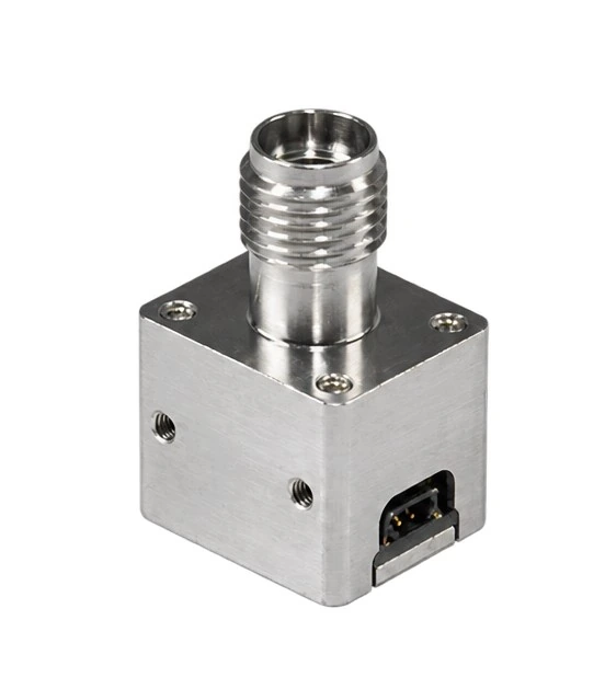
808 nm / 600 mW / SMA905 Packaged LPC laser power converter
FS-LPC-808-600mW-SMA905
Converts incident laser energy into DC electricity. Select the configuration against the optical interface, input conditions, load and heat sinking.

Parameters
| Reference designation | FS-LPC-808-600mW-SMA905 |
|---|---|
| Input wavelength | 800–840 nm |
| Typical operating points | 0.8536 W @ 1.5 W optical input / 6.0819 V / 0.1404 A |
| Maximum optical input (adequate cooling required) | 1.5 W |
| Operating case temperature | −40…+85 °C |
Applications & selection
Isolated power for industrial sensors; high-voltage equipment monitoring; remote electronics in high-EMI environments.
For enquiries: wavelength, optical power at the receiver, fiber connector or beam profile, target output, heat sinking and quantity.
Typical operating points
Operating points and curves: nominal wavelength, 25°C case temperature. Optical input is power at the receiver, not transmitter output or end-to-end electrical output.
| Optical input / W | Electrical Pmpp / W | Vmpp / V | Impp / A |
|---|---|---|---|
| 0.5 | 0.2726 | 6.0819 | 0.0448 |
| 1.0 | 0.5634 | 6.0822 | 0.0926 |
| 1.5 | 0.8536 | 6.0819 | 0.1404 |
| 2.0 | 1.1463 | 6.0823 | 0.1885 |
| 2.5 | 1.4321 | 6.1526 | 0.2328 |
The 2.0 W and 2.5 W optical-input points exceed the 1.5 W absolute maximum listed in the same reference. They are retained as reference records, not an allowed operating range; confirm the rating before selection.
Absolute maximum ratings / Fiber specifications
Absolute maximum ratings
| Parameter | Symbol | Min. | Typ. | Max. | Unit |
|---|---|---|---|---|---|
| Storage temperature | TS | −40 | 25 | 85 | °C |
| Operating case temperature | TC | −40 | — | 85 | °C |
| Relative humidity | RH | 5 | — | 85 | % |
| Optical input power limit | Popt IN | — | — | 1.5 | W |
Fiber specifications
| Parameter | Symbol | Min. | Typ. | Max. | Unit |
|---|---|---|---|---|---|
| Fiber core diameter | D | — | 40–400 (reference range) | — | μm |
| Numerical aperture | NA | 0.17 | 0.22 | 0.22 | — |
| Fiber length | — | — | Application-specific | — | m |
Pins & electrical interface
| 1 | − |
|---|---|
| 2 | + |
Images and pin assignments describe this reference configuration; other electrical interfaces or packages require separate confirmation.
Dimensions & mounting
Dimensions in mm; reference drawing. Confirm the latest engineering drawing before delivery.
Curves include reference test points above the absolute maximum; they do not define an allowed operating range.
Reference values support selection. Confirm final configuration and acceptance conditions in the technical agreement. A power class is not guaranteed output under every operating condition.